
Commercial Pump Sets - water circulation pump for water heater
Water velocityformula
The velocity calculations for pipes at steep grades are sensitive to tailwater conditions (or to the water levels in the downstream node).
Water velocityCalculator

In the second screenshot the nodes and links downstream of the steep link result in the downstream water level for that link to be high. The downstream water level is high, and as a result the water level at the mid point of the conduit is high – the pipe is approx half full. The high water level at mid point leads to a high cross section area of flow in the pipe and hence a (comparitively) low velocity. The calculated maximum velocity for the link shown in this configuration is 5.83m/s
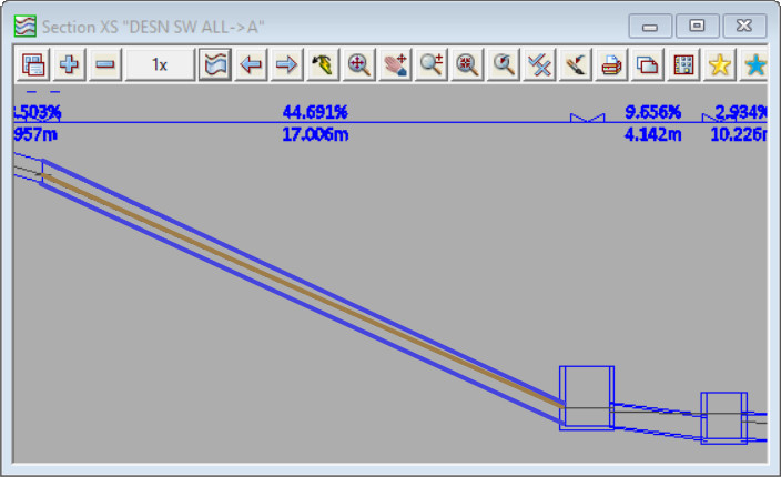
In the first screenshot below the tailwater level (the downstream water level) for the steep link is determined by 12d Model (using critical depth and normal depth equations). The downstream water level is low, and as a result the water level at the mid point of the conduit is low – the pipe is approx quarter full. The low water level at midpoint leads to a low cross section area of the flow in the pipe, and a hence a high velocity. The calculated maximum velocity for this link shown in this configuration is 9.05m/s
Water velocity in a pipeformula
Rinox Plus M and Plus Smart M series are membrane pressure reducers with inspectionable and easily interchangeable internal cartridge, complete with removable filter. The cartridge is a compensated seat: upstream pressure variations do not affect the adjustment of the downstream pressure.âRinoxPlus M pressure reducers are Watermark approved for potable water applications and are intended to be used in the plumbing, heating and sanitary systems with upstream pressure not higher than 16 bar. Controlled outlet range of 0.8 to 7 Bar.Rinox Due piston operated pressure reducing valves are suitable for use in systems that are subject to water hammering and can accept a nominal pressure of 25 bar. Controlled outlet range of 0.5 to 7 Bar.âRinox First are recommended for reducing the pressure between the distribution mains and themain use derivations. Rinox First can accept a nominal pressure of 40 Bar and maximumupstream pressure of 25 Bar. Controlled outlet range of 6 to 10 Bar.
Water velocity in pipeChart
Upstream velocity: calculated pipe max velocity us Mid-conduit velocity: calculated pipe max velocity Downstream velocity: calculated pipe max velocity ds
Water velocity in pipeCalculator
At EACH TIME STEP the Dynamic Drainage Engine performs the following calculations for each node and conduit in the network:
The RBM Rinox range of adjustable pressure reducing valves are available in either diaphragm operated or compensated piston operated. The main purpose of a pressure reducing valve or pressure limiting valve is to control the fluid pressure to an optimal value, constantly below the maximum allowed in order to avoid damaging the utilities placed downstream of the valve.The correct number of pressure reducers (PRVs) necessary for the pressure reduction is important to avoid cavitation. These phenomena, in fact, create an excessive noise in the reducer, with consequent problems for the utilities and possible damage of the reducer itself. For this reason, please refer to the dedicated section inside the technical data sheet for the optimal choice of the number of reducers in relation to the pressure variation to be obtained.

Under open channel conditions (part-full pipe flow) , the mid-channel depth is the average of the upstream and downstream depths. The velocity will be different at the upstream, mid-conduit, and downstream ends of the conduit.


 8615510865705
 8615510865705