
Febco RPZ Backflow Preventer 1 - rpz backflow preventer
Maximumvelocityinpipeformula
A pressure reducing valve operates through a pressure reducing pilot that senses and adjusts to downstream pressure. The pilot commands the valve to adjust—throttling or closing when pressure exceeds a set point and opening when it falls below, ensuring consistent output regardless of external changes.
Upstream velocity: calculated pipe max velocity us Mid-conduit velocity: calculated pipe max velocity Downstream velocity: calculated pipe max velocity ds
The velocity calculations for pipes at steep grades are sensitive to tailwater conditions (or to the water levels in the downstream node).
Watervelocity Calculator
At EACH TIME STEP the Dynamic Drainage Engine performs the following calculations for each node and conduit in the network:
WatervelocityinpipeChart
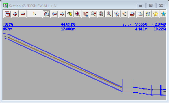
In the second screenshot the nodes and links downstream of the steep link result in the downstream water level for that link to be high. The downstream water level is high, and as a result the water level at the mid point of the conduit is high – the pipe is approx half full. The high water level at mid point leads to a high cross section area of flow in the pipe and hence a (comparitively) low velocity. The calculated maximum velocity for the link shown in this configuration is 5.83m/s
Water from city mains tends to be at high pressure, and can often fluctuate. Pressure reducing valves (PRV) reduce water pressure to a more suitable level, and help to regulate the pressure regardless of any fluctuations. See Bermad’s pressure reducing valves below.
Under open channel conditions (part-full pipe flow) , the mid-channel depth is the average of the upstream and downstream depths. The velocity will be different at the upstream, mid-conduit, and downstream ends of the conduit.
Calculatevelocityinpipefrom pressure
In the first screenshot below the tailwater level (the downstream water level) for the steep link is determined by 12d Model (using critical depth and normal depth equations). The downstream water level is low, and as a result the water level at the mid point of the conduit is low – the pipe is approx quarter full. The low water level at midpoint leads to a low cross section area of the flow in the pipe, and a hence a high velocity. The calculated maximum velocity for this link shown in this configuration is 9.05m/s
Velocity calculator for pipemetric
The choice of PRV depends on the specific needs of the application—considering factors like flow patterns, pipe characteristics, and system demands. Options vary from full bore designs for minimal pressure loss to specialized models designed to handle low flows or reduce cavitation.
Flowvelocity calculator for pipe
A Pressure Reducing Valve (PRV) is a type of valve that reduces a higher upstream pressure to a stable lower downstream pressure, irrespective of fluctuating demand or changing upstream pressure. These are essential in various settings, from municipal networks to high-rise buildings, ensuring protection against overpressure and maintaining sufficient pressure for effective use.
Municipal Systems: PRVs are crucial at the start of pressure zones or DMAs (District Metering Areas) to protect downstream equipment and household plumbing while ensuring reliable pressure for users. Irrigation: In agriculture, PRVs manage the water pressure for drip systems, pivot irrigation machines, and lower elevation fields to prevent damage and ensure efficient water distribution. High-Rise Buildings: Installed on each floor or every few floors, PRVs safeguard internal plumbing and fittings from excessive pressure, promoting longevity and safety.
PRVs can be mechanical, electronic, or hydraulic. Bermad specialises in fully automatic hydraulic PRVs, which are particularly efficient in managing variable flows and pressures.


 8615510865705
 8615510865705