
Hose Fittings & Adaptors - gas fittings
2024829 — Training and development specialists help create, plan, and run training programs for businesses and organizations. To do this, they must first ...
Supplementary oxygen may also be dispensed through a regulator which both reduces the pressure, and supplies the gas at a metered flow rate, to be mixed with ambient air.[8] One way of producing a constant mass flow at variable ambient pressure is to use a choked flow, where the flow through the metering orifice is sonic. For a given gas in choked flow, the mass flow rate may be controlled by setting the orifice size or the upstream pressure. To produce a choked flow in oxygen, the absolute pressure ratio of upstream and downstream gas must exceed 1.893 at 20 °C. At normal atmospheric pressure this requires an upstream pressure of more than 1.013 × 1.893 = 1.918 bar. A typical nominal regulated gauge pressure from a medical oxygen regulator is 3.4 bars (50 psi), for an absolute pressure of approximately 4.4 bar and a pressure ratio of about 4.4 without back pressure, so they will have choked flow in the metering orifices for a downstream (outlet) pressure of up to about 2.3 bar absolute. This type of regulator commonly uses a rotor plate with calibrated orifices and detents to hold it in place when the orifice corresponding to the desired flow rate is selected. This type of regulator may also have one or two uncalibrated takeoff connections from the intermediate pressure chamber with diameter index safety system (DISS) or similar connectors to supply gas to other equipment, and the high pressure connection is commonly a pin index safety system (PISS) yoke clamp.[9] Similar mechanisms can be used for flow rate control for aviation and mountaineering regulators.
Calculatevelocity in pipefrom pressure
Both types of regulator use feedback of the regulated pressure as input to the control mechanism, and are commonly actuated by a spring loaded diaphragm or piston reacting to changes in the feedback pressure to control the valve opening, and in both cases the valve should be opened only enough to maintain the set regulated pressure. The actual mechanism may be very similar in all respects except the placing of the feedback pressure tap.[2] As in other feedback control mechanisms, the level of damping is important to achieve a balance between fast response to a change in the measured pressure, and stability of output. Insufficient damping may lead to hunting oscillation of the controlled pressure, while excessive friction of moving parts may cause hysteresis.
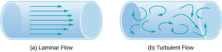
Another method for representing fluid motion is a streamline. A streamline represents the path of a small volume of fluid as it flows. The velocity is always tangential to the streamline. The diagrams in Figure use streamlines to illustrate two examples of fluids moving through a pipe. The first fluid exhibits a laminar flow (sometimes described as a steady flow), represented by smooth, parallel streamlines. Note that in the example shown in part (a), the velocity of the fluid is greatest in the center and decreases near the walls of the pipe due to the viscosity of the fluid and friction between the pipe walls and the fluid. This is a special case of laminar flow, where the friction between the pipe and the fluid is high, known as no slip boundary conditions. The second diagram represents turbulent flow, in which streamlines are irregular and change over time. In turbulent flow, the paths of the fluid flow are irregular as different parts of the fluid mix together or form small circular regions that resemble whirlpools. This can occur when the speed of the fluid reaches a certain critical speed.
What is the fluid speed in a fire hose with a 9.00-cm diameter carrying 80.0 L of water per second? (b) What is the flow rate in cubic meters per second? (c) Would your answers be different if salt water replaced the fresh water in the fire hose?
a. 12.6 m/s; b. [latex]0.0800\,{\text{m}}^{3}\text{/s}[/latex]; c. No, the flow rate and the velocity are independent of the density of the fluid.
Aerospace pressure regulators have applications in propulsion pressurant control for reaction control systems (RCS) and Attitude Control Systems (ACS), where high vibration, large temperature extremes and corrosive fluids are present.[4]
Watts OFPSYS OneFlow Plus Salt-Free Scale Prevention and Water Filtration System, Carbon Water Filter, Scale Reduction Cartridge, 1" NPT Inlet and Outlet ...
As the pressure in water pipes builds rapidly with depth, underground mining operations require a fairly complex water system with pressure reducing valves. These devices must be installed at a certain vertical interval, usually 600 feet (180 m).[citation needed] Without such valves, pipes could burst and pressure would be too great for equipment operation.
A nozzle with a diameter of 0.500 cm is attached to a garden hose with a radius of 0.900 cm. The flow rate through hose and nozzle is 0.500 L/s. Calculate the speed of the water (a) in the hose and (b) in the nozzle.
Flow rate and velocity are related, but quite different, physical quantities. To make the distinction clear, consider the flow rate of a river. The greater the velocity of the water, the greater the flow rate of the river. But flow rate also depends on the size and shape of the river. A rapid mountain stream carries far less water than the Amazon River in Brazil, for example. Figure illustrates the volume flow rate. The volume flow rate is [latex]Q=\frac{dV}{dt}=Av,[/latex] where [latex]A[/latex] is the cross-sectional area of the pipe and v is the magnitude of the velocity.
Watervelocity in pipeChart
The SI unit for flow rate is [latex]{\text{m}}^{3}\text{/s,}[/latex] but several other units for Q are in common use, such as liters per minute (L/min). Note that a liter (L) is 1/1000 of a cubic meter or 1000 cubic centimeters [latex]({10}^{-3}{\,\text{m}}^{3}\text{or}\,{10}^{3}\,{\text{cm}}^{3}).[/latex]
Two stage regulators are two regulators in series in the same housing that operate to reduce the pressure progressively in two steps instead of one. The first stage, which is preset, reduces the pressure of the supply gas to an intermediate stage; gas at that pressure passes into the second stage. The gas emerges from the second stage at a pressure (working pressure) set by user by adjusting the pressure control knob at the diaphragm loading spring. Two stage regulators may have two safety valves, so that if there is any excess pressure between stages due to a leak at the first stage valve seat the rising pressure will not overload the structure and cause an explosion.[citation needed]
11 Aug 2024 — Pressure: Expansion tank size is influenced by system pressure. Higher pressures need greater tanks in order to hold higher volumes of expanding ...
Pressure regulators are used extensively within the natural gas industry. Natural gas is compressed to high pressures in order to be distributed throughout the country through large transmission pipelines. The transmission pressure can be over 1,000 pounds per square inch (69 bar) and must be reduced through various stages to a usable pressure for industrial, commercial, and residential applications. There are three main pressure reduction locations in this distribution system. The first reduction is located at the city gate, whereas the transmission pressure is dropped to a distribution pressure to feed throughout the city. This is also the location where the odorless natural gas is odorized with mercaptan. The distribution pressure is further reduced at a district regulator station, located at various points in the city, to below 60 psig. The final cut would occur at the end users location. Generally, the end user reduction is taken to low pressures ranging from 0.25 psig to 5 psig. Some industrial applications can require a higher pressure.[citation needed]
We can use the relationship between flow rate and speed to find both speeds. We use the subscript 1 for the hose and 2 for the nozzle.
This is a reduced pressure assembly. The 1/2"-2" sizes began production in 1997. The body is made of bronze and utilizes an in-line modular check design.
An unbalanced single stage regulator may need frequent adjustment. As the supply pressure falls, the outlet pressure may change, necessitating adjustment. In the two stage regulator, there is improved compensation for any drop in the supply pressure.[citation needed]
What is the average flow rate in [latex]{\text{cm}}^{3}\text{/s}[/latex] of gasoline to the engine of a car traveling at 100 km/h if it averages 10.0 km/L?
The volume of fluid passing by a given location through an area during a period of time is called flow rate Q, or more precisely, volume flow rate. In symbols, this is written as
For recreational vehicles with plumbing, a pressure regulator is required to reduce the pressure of an external water supply connected to the vehicle plumbing, as the supply may be a much higher elevation than the campground, and water pressure depends on the height of the water column. Without a pressure regulator, the intense pressure encountered at some campgrounds in mountainous areas may be enough to burst the camper's water pipes or unseat the plumbing joints, causing flooding. Pressure regulators for this purpose are typically sold as small screw-on accessories that fit inline with the hoses used to connect an RV to the water supply, which are almost always screw-thread-compatible with the common garden hose.[citation needed]
All propane and LP gas applications require the use of a regulator. Because pressures in propane tanks can fluctuate significantly with temperature, regulators must be present to deliver a steady pressure to downstream appliances. These regulators normally compensate for tank pressures between 30–200 pounds per square inch (2.1–13.8 bar) and commonly deliver 11 inches water column 0.4 pounds per square inch (28 mbar) for residential applications and 35 inches of water column 1.3 pounds per square inch (90 mbar) for industrial applications. Propane regulators differ in size and shape, delivery pressure and adjustability, but are uniform in their purpose to deliver a constant outlet pressure for downstream requirements. Common international settings for domestic LP gas regulators are 28 mbar for butane and 37 mbar for propane.
Air compressors are used in industrial, commercial, and home workshop environments to perform an assortment of jobs including blowing things clean; running air powered tools; and inflating things like tires, balls, etc. Regulators are often used to adjust the pressure coming out of an air receiver (tank) to match what is needed for the task. Often, when one large compressor is used to supply compressed air for multiple uses (often referred to as "shop air" if built as a permanent installation of pipes throughout a building), additional regulators will be used to ensure that each separate tool or function receives the pressure it needs. This is important because some air tools, or uses for compressed air, require pressures that may cause damage to other tools or materials.[citation needed]
Many figures in the text show streamlines. Explain why fluid velocity is greatest where streamlines are closest together. (Hint: Consider the relationship between fluid velocity and the cross-sectional area through which the fluid flows.)
PLT12. Diaphragm Type, Butyl Rubber. Inlet/Outlet Connection, 3/4 Inch Male Threaded. Manufacturer Part Number Additional, PLT-12. Pressure Rating, 150 PSI.
A pressure regulator is a valve that controls the pressure of a fluid to a desired value, using negative feedback from the controlled pressure. Regulators are used for gases and liquids, and can be an integral device with a pressure setting, a restrictor and a sensor all in the one body, or consist of a separate pressure sensor, controller and flow valve.
where A is the cross-sectional area and [latex]v[/latex] is the average speed. The relationship tells us that flow rate is directly proportional to both the average speed of the fluid and the cross-sectional area of a river, pipe, or other conduit. The larger the conduit, the greater its cross-sectional area. Figure illustrates how this relationship is obtained. The shaded cylinder has a volume [latex]V=Ad[/latex], which flows past the point P in a time t. Dividing both sides of this relationship by t gives
The first part of this chapter dealt with fluid statics, the study of fluids at rest. The rest of this chapter deals with fluid dynamics, the study of fluids in motion. Even the most basic forms of fluid motion can be quite complex. For this reason, we limit our investigation to ideal fluids in many of the examples. An ideal fluid is a fluid with negligible viscosity. Viscosity is a measure of the internal friction in a fluid; we examine it in more detail in Viscosity and Turbulence. In a few examples, we examine an incompressible fluid—one for which an extremely large force is required to change the volume—since the density in an incompressible fluid is constant throughout.
Pressure regulators are used with diving cylinders for Scuba diving. The tank may contain pressures in excess of 3,000 pounds per square inch (210 bar), which could cause a fatal barotrauma injury to a person breathing it directly. A demand controlled regulator provides a flow of breathing gas at the ambient pressure (which varies by depth in the water). Pressure reducing regulators are also use to supply breathing gas to surface-supplied divers,[5] and people who use self-contained breathing apparatus (SCBA) for rescue and hazmat work on land. The interstage pressure for SCBA at normal atmospheric pressure can generally be left constant at a factory setting, but for surface supplied divers it is controlled by the gas panel operator, depending on the diver depth and flow rate requirements. Supplementary oxygen for high altitude flight in unpressurised aircraft and medical gases are also commonly dispensed through pressure reducing regulators from high-pressure storage.[6][7]
Water is moving at a velocity of 2.00 m/s through a hose with an internal diameter of 1.60 cm. (a) What is the flow rate in liters per second? (b) The fluid velocity in this hose’s nozzle is 15.0 m/s. What is the nozzle’s inside diameter?
836859 | Cooling Spare Parts | Fisher & Paykel Australia.
It achieves this by constantly monitoring the temperature of the water it mixes. Based on this monitoring, the valve adjusts the amount of hot and cold water, ...
Maximumvelocity in pipeformula
Prove that the speed of an incompressible fluid through a constriction, such as in a Venturi tube, increases by a factor equal to the square of the factor by which the diameter decreases. (The converse applies for flow out of a constriction into a larger-diameter region.)
As leading inventor and manufacturer of safe, high-quality stainless-steel gas connectors, Dormont has earned the reputation as one of the foremost experts .
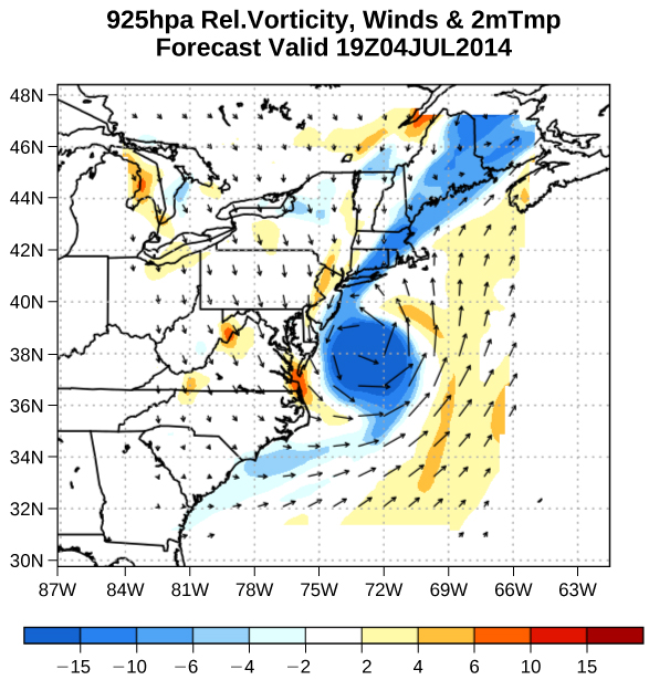
Velocity vectors are often used to illustrate fluid motion in applications like meteorology. For example, wind—the fluid motion of air in the atmosphere—can be represented by vectors indicating the speed and direction of the wind at any given point on a map. Figure shows velocity vectors describing the winds during Hurricane Arthur in 2014.
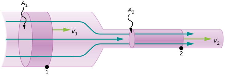
Figure shows an incompressible fluid flowing along a pipe of decreasing radius. Because the fluid is incompressible, the same amount of fluid must flow past any point in the tube in a given time to ensure continuity of flow. The flow is continuous because they are no sources or sinks that add or remove mass, so the mass flowing into the pipe must be equal the mass flowing out of the pipe. In this case, because the cross-sectional area of the pipe decreases, the velocity must necessarily increase. This logic can be extended to say that the flow rate must be the same at all points along the pipe. In particular, for arbitrary points 1 and 2,
A water pressure regulating valve limits inflow by dynamically changing the valve opening so that when less pressure is on the outside, the valve opens up fully, and too much pressure on the outside causes the valve to shut. In a no pressure situation, where water could flow backwards, it won't be impeded. A water pressure regulating valve does not function as a check valve.[citation needed][clarification needed]
All vehicular motors that run on compressed gas as a fuel (internal combustion engine or fuel cell electric power train) require a pressure regulator to reduce the stored gas (CNG or Hydrogen) pressure from 700, 500, 350 or 200 bar (or 70, 50, 35 and 20 MPa) to operating pressure.[citation needed])
A pressure reducing regulator's primary function is to match the flow of gas through the regulator to the demand for fluid placed upon it, whilst maintaining a sufficiently constant output pressure. If the load flow decreases, then the regulator flow must decrease as well. If the load flow increases, then the regulator flow must increase in order to keep the controlled pressure from decreasing because of a shortage of fluid in the pressure system. It is desirable that the controlled pressure does not vary greatly from the set point for a wide range of flow rates, but it is also desirable that flow through the regulator is stable and the regulated pressure is not subject to excessive oscillation.[citation needed]
Gasvelocity in pipeCalculator
where [latex]\rho[/latex] is the density, A is the cross-sectional area, and v is the magnitude of the velocity. The mass flow rate is an important quantity in fluid dynamics and can be used to solve many problems. Consider Figure. The pipe in the figure starts at the inlet with a cross sectional area of [latex]{A}_{1}[/latex] and constricts to an outlet with a smaller cross sectional area of [latex]{A}_{2}[/latex]. The mass of fluid entering the pipe has to be equal to the mass of fluid leaving the pipe. For this reason the velocity at the outlet [latex]({v}_{2})[/latex] is greater than the velocity of the inlet [latex]({v}_{1})[/latex]. Using the fact that the mass of fluid entering the pipe must be equal to the mass of fluid exiting the pipe, we can find a relationship between the velocity and the cross-sectional area by taking the rate of change of the mass in and the mass out:
Pressure regulators are found in aircraft cabin pressurization, canopy seal pressure control, potable water systems, and waveguide pressurization.[3]
Water emerges straight down from a faucet with a 1.80-cm diameter at a speed of 0.500 m/s. (Because of the construction of the faucet, there is no variation in speed across the stream.) (a) What is the flow rate in [latex]{\text{cm}}^{3}\text{/s}[/latex]? (b) What is the diameter of the stream 0.200 m below the faucet? Neglect any effects due to surface tension.
A speed of 1.96 m/s is about right for water emerging from a hose with no nozzle. The nozzle produces a considerably faster stream merely by constricting the flow to a narrower tube.
Figure is also known as the continuity equation in general form. If the density of the fluid remains constant through the constriction—that is, the fluid is incompressible—then the density cancels from the continuity equation,
(a) Estimate the time it would take to fill a private swimming pool with a capacity of 80,000 L using a garden hose delivering 60 L/min. (b) How long would it take if you could divert a moderate size river, flowing at [latex]{5000\,\text{m}}^{3}\text{/s}[/latex] into the pool?
Pipeflowvelocityrule of thumb
The rate of flow of a fluid can also be described by the mass flow rate or mass rate of flow. This is the rate at which a mass of the fluid moves past a point. Refer once again to Figure, but this time consider the mass in the shaded volume. The mass can be determined from the density and the volume:
According to regulatory standards any water filter system under constant water pressure [regardless of the brand or supplier] is required to be fitted with an ...
f : poppet spring force {\displaystyle f:{\text{ poppet spring force}}} P i : inlet pressure {\displaystyle P_{i}:{\text{ inlet pressure}}} P o : outlet pressure {\displaystyle P_{o}:{\text{ outlet pressure}}} s : poppet area {\displaystyle s:{\text{ poppet area}}}
20131120 — Basically, the higher the upstream pressure, the more pressure the regulator can handle before it trips (or opens) the valve.
Oxy-fuel welding and cutting processes require gases at specific pressures, and regulators will generally be used to reduce the high pressures of storage cylinders to those usable for cutting and welding. Oxygen and fuel gas regulators usually have two stages: The first stage of the regulator releases the gas at a constant pressure from the cylinder despite the pressure in the cylinder becoming less as the gas is released. The second stage of the regulator controls the pressure reduction from the intermediate pressure to low pressure. The final flow rate may be adjusted at the torch. The regulator assembly usually has two pressure gauges, one indicating cylinder pressure, the other indicating delivery pressure. Inert gas shielded arc welding also uses gas stored at high pressure provided through a regulator. There may be a flow gauge calibrated to the specific gas.[citation needed]
Where the pressure drop on a built-in breathing system exhaust system is too great, typically in saturation systems, a back-pressure regulator may be used to reduce the exhaust pressure drop to a safer and more manageable pressure.[10][12]
This is called the equation of continuity and is valid for any incompressible fluid (with constant density). The consequences of the equation of continuity can be observed when water flows from a hose into a narrow spray nozzle: It emerges with a large speed—that is the purpose of the nozzle. Conversely, when a river empties into one end of a reservoir, the water slows considerably, perhaps picking up speed again when it leaves the other end of the reservoir. In other words, speed increases when cross-sectional area decreases, and speed decreases when cross-sectional area increases.
Velocity in pipeCalculator
The Huka Falls on the Waikato River is one of New Zealand’s most visited natural tourist attractions. On average, the river has a flow rate of about 300,000 L/s. At the gorge, the river narrows to 20-m wide and averages 20-m deep. (a) What is the average speed of the river in the gorge? (b) What is the average speed of the water in the river downstream of the falls when it widens to 60 m and its depth increases to an average of 40 m?
They are used in applications where the water pressure is too high at the end of the line to avoid damage to appliances or pipes.
We note that [latex]Q=V\text{/}t[/latex] and the average speed is [latex]v\text{ }=d/t[/latex]. Thus the equation becomes [latex]Q=Av[/latex].
The depth at which most heliox breathing mixtures are used in surface-supplied diving is generally at least 5 bar above surface atmospheric pressure, and the exhaust gas from the diver must pass through a reclaim valve, which is a back-pressure valve activated by the increase in pressure in the diver's helmet above ambient pressure caused by diver exhalation.[13][14] The reclaim gas hose which carries the exhaled gas back to the surface for recycling must not be at too great a pressure difference from the ambient pressure at the diver. An additional back-pressure regulator in this line allows finer setting of the reclaim valve for lower work of breathing at variable depths.[15]
Velocity in pipeCalculator metric
Consider two different pipes connected to a single pipe of a smaller diameter, with fluid flowing from the two pipes into the smaller pipe. Since the fluid is forced through a smaller cross-sectional area, it must move faster as the flow lines become closer together. Likewise, if a pipe with a large radius feeds into a pipe with a small radius, the stream lines will become closer together and the fluid will move faster.
The solution to the last part of the example shows that speed is inversely proportional to the square of the radius of the tube, making for large effects when radius varies. We can blow out a candle at quite a distance, for example, by pursing our lips, whereas blowing on a candle with our mouth wide open is quite ineffective.
Velocity in pipeformula
The outlet pressure on the diaphragm and the inlet pressure and poppet spring force on the upstream part of the valve hold the diaphragm/poppet assembly in the closed position against the force of the diaphragm loading spring. If the supply pressure falls, the closing force due to supply pressure is reduced, and downstream pressure will rise slightly to compensate. Thus, if the supply pressure falls, the outlet pressure will increase, provided the outlet pressure remains below the falling supply pressure. This is the cause of end-of-tank dump where the supply is provided by a pressurized gas tank.[citation needed] The operator can compensate for this effect by adjusting the spring load by turning the knob to restore outlet pressure to the desired level. With a single stage regulator, when the supply pressure gets low, the lower inlet pressure causes the outlet pressure to climb. If the diaphragm loading spring compression is not adjusted to compensate, the poppet can remain open and allow the tank to rapidly dump its remaining contents.[citation needed]
Since liquids are essentially incompressible, the equation of continuity is valid for all liquids. However, gases are compressible, so the equation must be applied with caution to gases if they are subjected to compression or expansion.
High pressure gas from the supply enters the regulator through the inlet port. The inlet pressure gauge will indicate this pressure. The gas then passes through the normally open pressure control valve orifice and the downstream pressure rises until the valve actuating diaphragm is deflected sufficiently to close the valve, preventing any more gas from entering the low pressure side until the pressure drops again. The outlet pressure gauge will indicate this pressure.[citation needed]
The heart of a resting adult pumps blood at a rate of 5.00 L/min. (a) Convert this to [latex]{\text{cm}}^{3}\text{/s}[/latex]. (b) What is this rate in [latex]{\text{m}}^{3}\text{/s}[/latex]?
In the pictured single-stage regulator, a force balance is used on the diaphragm to control a poppet valve in order to regulate pressure. With no inlet pressure, the spring above the diaphragm pushes it down on the poppet valve, holding it open. Once inlet pressure is introduced, the open poppet allows flow to the diaphragm and pressure in the upper chamber increases, until the diaphragm is pushed upward against the spring, causing the poppet to reduce flow, finally stopping further increase of pressure. By adjusting the top screw, the downward pressure on the diaphragm can be increased, requiring more pressure in the upper chamber to maintain equilibrium. In this way, the outlet pressure of the regulator is controlled.[citation needed]
Pressurized vessels can be used to cook food much more rapidly than at atmospheric pressure, as the higher pressure raises the boiling point of the contents. All modern pressure cookers will have a pressure regulator valve and a pressure relief valve as a safety mechanism to prevent explosion in the event that the pressure regulator valve fails to adequately release pressure. Some older models lack a safety release valve[citation needed]. Most home cooking models are built to maintain a low and high pressure setting. These settings are usually 7 to 15 pounds per square inch (0.48 to 1.03 bar). Almost all home cooking units will employ a very simple single-stage pressure regulator. Older models will simply use a small weight on top of an opening that will be lifted by excessive pressure to allow excess steam to escape. Newer models usually incorporate a spring-loaded valve that lifts and allows pressure to escape as pressure in the vessel rises. Some pressure cookers will have a quick release setting on the pressure regulator valve that will, essentially, lower the spring tension to allow the pressure to escape at a quick, but still safe rate. Commercial kitchens also use pressure cookers, in some cases using oil based pressure cookers to quickly deep fry fast food. Pressure vessels of this sort can also be used as autoclaves to sterilize small batches of equipment and in home canning operations.[citation needed]
[latex]Q={A}_{1}{\overset{\text{–}}{v}}_{1}={A}_{2}{\overset{\text{–}}{v}}_{2},[/latex] or [latex]\pi \frac{{d}_{1}^{2}}{4}{\overset{\text{–}}{v}}_{1}=\pi \frac{{d}_{2}^{2}}{4}{\overset{\text{–}}{v}}_{2}\Rightarrow {\overset{\text{–}}{v}}_{2}={\overset{\text{–}}{v}}_{1}({d}_{1}^{2}\text{/}{d}_{2}^{2})={\overset{\text{–}}{v}}_{1}{({d}_{1}\text{/}{d}_{2})}^{2}[/latex]


 8615510865705
 8615510865705