
Vacuum Breaker 13mm - 1 4 vacuum breaker
Calculatevelocity in pipefrom pressure
Under open channel conditions (part-full pipe flow) , the mid-channel depth is the average of the upstream and downstream depths. The velocity will be different at the upstream, mid-conduit, and downstream ends of the conduit.
Velocity in pipeCalculator
The velocity calculations for pipes at steep grades are sensitive to tailwater conditions (or to the water levels in the downstream node).
Water is stored in a bladder within the tank vessel opposite pressurized air. As the bladder fills, the back pressure increases until it reaches a pre-set pressure limit (as determined by the shut-off valve, sold separately), causing the shut-off valve to cut off the feed supply to the reverse osmosis system. Water will remain in the bladder until the faucet is opened, the air pressure surrounding the bladder will force the water out of the storage tank and a directed point of use. As water is used, the pressure will drop until the shut-off valve disengages, allowing feed water to the RO system to resume until the tank is refilled.
At EACH TIME STEP the Dynamic Drainage Engine performs the following calculations for each node and conduit in the network:
Velocity of water in a pipeformula
A pressurized storage tank for reverse osmosis product water is recommended for its ability to deliver reverse osmosis water to the faucet using air pressure within the tank. The system shut-off valve (sold separately), will automatically turn the RO system on and off as needed.
Velocity of water in a pipecalculator
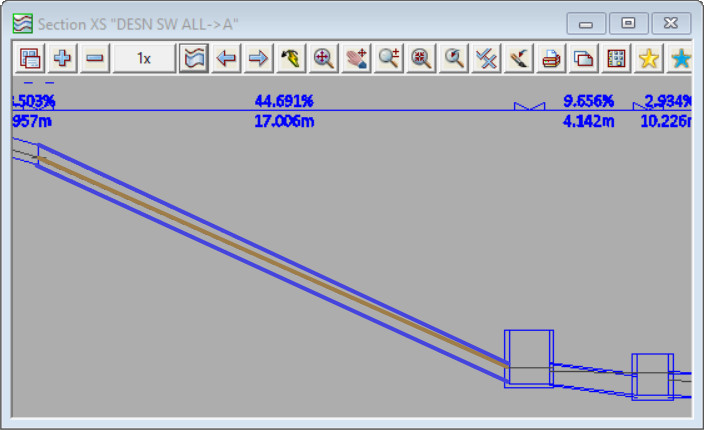
In the second screenshot the nodes and links downstream of the steep link result in the downstream water level for that link to be high. The downstream water level is high, and as a result the water level at the mid point of the conduit is high – the pipe is approx half full. The high water level at mid point leads to a high cross section area of flow in the pipe and hence a (comparitively) low velocity. The calculated maximum velocity for the link shown in this configuration is 5.83m/s
Water velocityformula
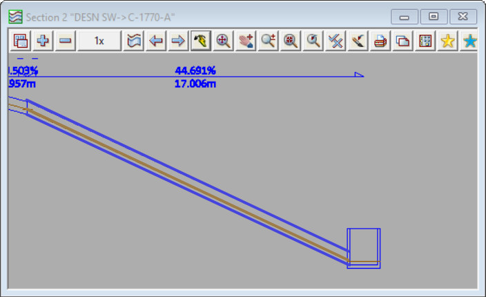
In the first screenshot below the tailwater level (the downstream water level) for the steep link is determined by 12d Model (using critical depth and normal depth equations). The downstream water level is low, and as a result the water level at the mid point of the conduit is low – the pipe is approx quarter full. The low water level at midpoint leads to a low cross section area of the flow in the pipe, and a hence a high velocity. The calculated maximum velocity for this link shown in this configuration is 9.05m/s
Upstream velocity: calculated pipe max velocity us Mid-conduit velocity: calculated pipe max velocity Downstream velocity: calculated pipe max velocity ds
Applied Membranes, Inc. is committed to customer service that exceeds your expectations. For prompt, courteous and reliable service, contact us today!
Water velocity in pipeChart
JavaScript seems to be disabled in your browser. You must have JavaScript enabled in your browser to utilize the functionality of this website.
For commercial RO pressurized storage tanks up to 80 gallon capacity, view our Flexwave Commercial RO Storage Tanks product line.


 8615510865705
 8615510865705