
Watts 0887708 1 1/4-2 Backflow Rubber Repair Kit, 800M4 - 800m4 repair kit
Snow meltmats
Radiant Heat Manifolds · 2 Loop Stainless Steel Radiant Heat Manifold Set With 1/2″ PEX Adapters · 3 Loop Stainless Steel Radiant Heat Manifold Set With 1/2″ ...
The Tekmar 257 for instance, is a boiler control system - a maestro if you will, that ensures optimal performance by operating multiple boilers in symphony.
Powers e428 HydroGuard exposed thermostatic mixing valve for tempered domestic potable water applications. This valve features a built-in shutoff valve for ...
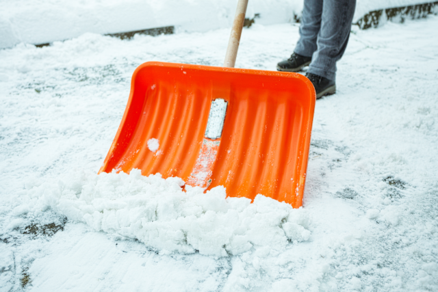
LaBella has designed multiple hot water snow melt system installations for sidewalks, roads, and truck ramps. Snow melt systems reduce the risk of injuries from slipping, eliminate the physical labor (and cost) of shoveling and plowing, minimize accidents caused by icy roads, and improve the aesthetic appeal of pathways and driveways.
Electraulic Actuation is a brand of electro-hydraulic actuation unique to REXA. It combines the simplicity of electric operation, the power of hydraulics, the reliability of solid state electronics, and the flexibility of user-configured control.
Electricsnow meltsystem
TVS XL 100 BS6 is a comfortable & heavy-duty moped bike for easy rides & load-carrying business. Check out XL100 price, mileage, colors & specifications ...
Ice damming can also occur when sunny days melt snow on dark roof surfaces. Snow melts fastest at peaks where the highest concentrations of heat are located. Water drips down to the roof’s edge, where it meets frigid air temperatures and a cold roof due to an unheated space below and freezes into an ice dam. As snow continues to melt, it backs up behind the ice dam and dangerous icicles form along the roof edge. These dams are exacerbated when outdoor air temperatures fluctuate – warmer winter days cause increased ice and snow melting.
Snow meltsystem for roof
At LaBella Associates, we’ve built partnerships with our clients since our inception in 1978. If there’s been a need, we’ve responded. The result? Diverse service offerings that can address any aspect of the built or natural environment.
When operating pressure acting from the inlet of a safety valve is less than the spring force pushing down, the safety valve is closed as shown in Figure 3. For a safety valve to maintain seat tightness, the operating pressure should typically be equal to or less than 95% of the set pressure.
Once the safety valve has opened, the position of the upper adjusting ring forces the steam to change direction, creating additional lift. These additional forces cause the disc to achieve full lift. Full lift can be attained by proper location of the upper adjusting ring (G) and lower adjusting ring (O), respectively. When full lift is attained, as shown in Figure 5, the lift stop (M) rests against the cover plate (P) to eliminate hunting, thus adding stability to the valve. When the safety valve is in the open position, steam is bled into chamber (H) through two bleed holes (J) in the roof of the disc holder. Similarly, the spindle overlap collar (K) rises to a fixed position above the floating washer (L). The area between the floating washer and the spindle is thereby increased by the difference in the two diameters on the overlap collar. Under this condition, steam (H) enters into chamber (Q) through the secondary area formed by the floating washer (L) and the overlap collar (K) on the spindle, then through orifice (N) and escapes to atmosphere through the pipe discharge connection (R). Additional steam will flow through the area between the floating washer (L) and the overlap collar (K).
Course Details & Benefits: · Pricing. 6-Hour Continuing Education for Plumbers: $159 per session · State Approved · Course Integrity · Instant Certificate ...
When operating pressure increases until the simmer point, as shown in Figure 4, steam will move past the seating surfaces into the huddling chamber. Flow restriction in the secondary annular orifice formed between the upper adjusting ring (G) and lower adjusting ring (O) causes pressure to build up and act over a larger area, creating an additional force to overcome the spring force. The disc will then move away from the seat bushing and the valve will “pop” open at set pressure.
Snowmelting system
This is where clients blend with teams. Where need meets know-how. See how our breadth of service can tackle your industry’s toughest challenges.
Electric ice melt systems for roofs eliminate ice damming at the eaves of buildings. When rooms in a building are heated, that warm air raises to the attic and can melt lower layers of snow on the roof. The melted snow runs to the edge of the roof, where it freezes. As more and more snow melts and then turns to ice, the ice dam makes its way up the roof and seeps underneath the shingles. This process results in dangerous water damage and the potential for mold growth.
Snow meltseltzer
LaBella has partnered with many municipalities to design these systems with efficiency, effectiveness, and safety in mind. If you have a problem area and would like to explore the feasibility of constructing one of these systems, contact us today.
Snow meltalcohol
In the past two issues of this publication, we have covered the fundamental operating principles and applications for spring-loaded safety relief valves and pilot-operated safety relief valves (POSRV). In this last installment of the three-part series, we will focus on the fundamental operation of safety valves and common applications.
A safety valve (SV) is a spring-loaded pressure relief valve actuated by the static pressure upstream of the valve, characterized by rapid opening or “pop” action. A safety valve is normally used on compressible fluids, primarily steam. These devices are typically certified to protect the system within 3% overpressure, which is the rise in pressure above the maximum allowable working pressure (MAWP) of the equipment being protected.
Relief Valve-Watts M15 is a high-quality valve designed for optimal performance and durability. This relief valve is compatible with Z21.22 m15 std. z21.22 ...
Snowmeltingsystemsfor concrete slabs
2017119 — The MetroMix is packaged with a rugged stainless steel valve body and a reliable electronic actuator. These valves are designed to provide lead- ...
The thermodisc (marked P in Figure 6) stits on the seat bushing and makes up the seating surface of the safety valve. Often made of Inconel for its superior corrosive resistance, it minimizes distortion to the spindle/disc contact area under temperature, load or impact during safety valve actuation. Thus, the safety valve can achieve a reliable seat tightness of 95% of set pressure. The thermodisc has a unique design with a thin flexible lip which enables the seat to retain flexibility, especially under steam conditions, where it is usually higher in temperature and pressure. The thin flexible lip design enables the disc temperature to quickly equalize with the steam temperature, reducing distortions caused by the steam throttling to atmosphere. This lip design enables the system pressure to assist the mechanical loading. A line contact at the sealing surface of the seat bushing is created which improves the seat tightness. The critical seating area remains constant, ensuring a consistent safety valve set pressure. The thermodisc provides a low spindle bearing point for the spring force to transmit below the horizontal seating line of the safety valve. It equalizes spring force distribution to the safety valve seat area and minimizes the natural tendency for the disc to assume a horizontal tilted position. It remains concentric to the bushing centerline which assures reseating to the original position and prevents damage caused by any misalignment.
Two side rods are located outside of the safety valve body and installed so they are away from the high temperature of the boiler and the side rod temperatures remain relatively constant. The two side rods allow the thermal expansion of the safety valve body, caused by the high temperature of the boiler, without having a negative effect on the safety valve performance. Thus, spring-loaded models are relatively constant, and set pressure is predictable and does not vary with changes in the heat flow pattern.
An ice melt system consisting of de-icing cables that run along the roof and through gutters and downspouts can prevent the occurrence of the ice damming. The electric cabling, being constant wattage, should not be overlaid and should be carefully installed to avoid overheating and possible short circuiting. LaBella Associates can work to design an effective ice melt system and can oversee construction to ensure proper installation.
When closing, as shown in Figure 6, the spindle overlap collar (K) moves down into the floating washer (L), thereby effectively reducing the escape of steam from chamber (H). The resulting momentary pressure building up in chamber (H), at a rate controlled by orifice (N), produces a downward thrust in the direction of the spring loading. The combined thrust of the pressure and the spring loading results in positive and precise closing. During closing, the force of trapped steam on the upper side of the disc holder is utilized to assist the spring in forcing the disc back down onto the seat. Cushioning of the closing is controlled by the lower adjusting ring (O).
Hydronicsnow meltsystem
As this series concludes, the journey through the basics of pressure relief valves sheds light on the different valve types that are out there safeguarding our industrial landscapes — spring-loaded safety relief, pilot-operated safety relief and safety valves — and their operational and application differences. These devices are a critical last line of defense for the protection of people and property from overpressure events in systems.
These spring-loaded valves provide overpressure protection for downstream equipment. #pressure-relief #basics #knowyourvalves

Blowdown can be achieved by adjusting the upper adjusting ring, along with the lower adjusting ring (marked O in Figure 5), to have a short simmer and a good clean pop at set pressure. By properly fine-tuning of the overlap collar (marked K in Figure 5), 3% blowdown can be attained through pressure-assisted closing.
Wai Loon Cheong is the valves training leader for Baker Hughes. He has more than 20 years experience, and has worked in a variety of roles at the company.
2023817 — I have a standby hot water tank fed via a gas furnace. I have a 1/2hp circulator pump for a bathroom with a dedicated hot water return line.
2021717 — I personally think that the Roland V-Drum modules (I'm using a TD-30) offer infinitely better playability than SD3.
There are two types of heating systems that melt snow and ice – electric and hydronic. Electric systems draw from the building’s power and use that energy to heat coils. These are typically best suited for melting dangerous ice that forms on roofs. Electric snow melt systems aren’t typically recommended for pathways and roads because they raise utility bills and can be affected by power outages. Hydronic systems, on the other hand, use hot water or steam from a boiler and are a more economic option for heating ground surfaces.
Back in the “early days,” we were taught that, to properly control flow, we should select a linear valve characteristic when the valve controls more than 25% of the piping system pressure drop at full flow.
Safety valves are typically provided for the power industry. However, they are also used in other industries such as refining/petrochemical, chemical, pulp and paper, metals and mining, and textiles where boilers are used for power generation. Some common applications for safety valves include boiler drums, superheaters, reheaters, economizers, feedwater heaters and in other plant applications.
Both snow melt and ice melt systems are designed to turn on automatically when they are needed. For driveways, roads, and pathways, a moisture- and- temperature-sensing “puck” turns on the system when it detects moisture and temperatures close to freezing. Electric roof heating systems are triggered by a temperature-sensing puck or wire.
Full lift at set pressure can be achieved by rapidly venting steam through the cover plate (marked P in Figure 5). During discharge of the safety valve, the cover plate redirects the steam to a safe location. Thus, it isolates the spring from the steam temperature, which reduces spring relaxation.

Typically, the spring is exposed and visible without the need for valve disassembly. Safety valves come in two predominant designs — the robust side-rod construction (Figure 1), suitable for high-pressure and temperature applications, and the versatile yoke design, used for lower pressure and temperature applications (Figure 2).
The regulator is set to deliver water to the boiler at approximately 15 lbs. ... To reset the regulator valve: Remove the fast fill lever cap, and loosen the ...


 8615510865705
 8615510865705