
Backflow Preventers - reduced pressure backflow preventer
Hydronicsnow meltsystem design

Every year, a typical family of three living in a household fitted with a conventional one string plumbing system pours up to 16,000 litres of clean water straight down the drain - for no good reason at all. Every time they turn on a hot water tap or a shower, they wait an average of 60 seconds for the water to run hot. This wastes approximately 1,5 decilitres of water per second.
Snow meltmats
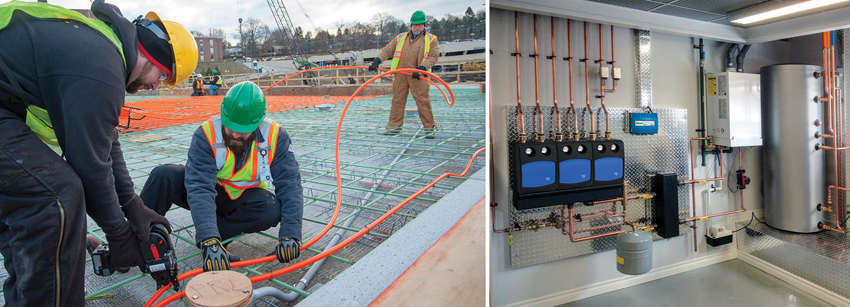
Electrical snow-melting systems can use preassembled mats of wire (left) or hand-installed coils of electrical wire (right). The preassembled mats have the advantage of ensuring a uniform spacing and streamlined installation.
*The figures are based on a report by Dr. Ing. Hugo Feurich VDI and calculated as a typical household of three persons each wasting 15 litres of clean water on waiting for hot water per day.
Some further design criteria for different system types follows. Photos courtesy of WattsHydronic snow-melting systems rely on the same basic components as other hydronic systems: a boiler, distribution piping and manifolds, zone controls, pumps, and tubing for the radiant snow melting. Supply and return piping needs to be insulated, and pre-insulated products are available for this specific purpose. Hydronic System Design The design of a hydronic snow-melting system is similar to other hydronic systems used for other purposes. Keep in mind that hydronic snow-melting systems not using a dedicated heat source will use a heat exchanger at the piping interface. This added component needs to be factored into the mechanical room requirements. The heat transfer medium in the hydronic systems is based on using water and a glycol mix with calculations made accordingly. Other design considerations include the following: Temperature: The water temperature should be designed for 100–150 degrees Fahrenheit. This temperature can be fluctuated in a hydronic system as needed for a particular design depending on the mass of the surface, differing conditions, and the snow-melting time cycle desired (i.e., 4, 5, or 6 hours). Pipe size: It is common to use ½-inch-diameter pipe or larger depending on the length and area of the snow-melting location. Supply/return pipe insulation: The distance between the boiler/heat exchanger and the surface where the snow-melting system is installed will require supply and return transmission piping. All of this piping will need to be insulated to ensure that the heat is applied as intended and not lost along the way. Snow-melting insulation: Placing insulation under a snow-melting system is generally viewed as optional and is not normally used. However, there may be cases where it is necessary based on the application, performance factors, or regulatory requirements. Piping layout: The length of the hydronic piping (or tubing) should be considered in a layout. Typically, longer runs mean more pressure drop, which affects the performance and size of the pumps used to move the water/glycol mix. Piping spacing: The spacing distance between parallel piping tubes is important. The general guideline is to space tubing between 6–12 inches on center, with a 9-inch spacing being most typical. The use of a 6-inch tube spacing is typical for critical use areas, such as a hospital entrance, handicapped ramps, parking garage ramps, etc. Spacing that is wider than 12 inches will tend to cause striping of the snow/ice and not melt the surface area completely, so spacing of more than 12 inches should be avoided. Depth of pipe: The piping/tubing needs to be close enough to the surface to be effective but must remain covered. Therefore, it should be no closer than 2–3 inches from the surface for proper protection. It should also be no deeper than needed since the further down it is, the slower the response rate and the more energy that will be needed to operate the system. Photos courtesy of WattsElectrical snow-melting systems can use preassembled mats of wire (left) or hand-installed coils of electrical wire (right). The preassembled mats have the advantage of ensuring a uniform spacing and streamlined installation.
Hydronic snow-melting systems rely on the same basic components as other hydronic systems: a boiler, distribution piping and manifolds, zone controls, pumps, and tubing for the radiant snow melting.
Snow meltsystem for roof
Electricsnow meltsystem
With all of the site conditions, design parameters, and expectations sorted out, it is then appropriate to design and engineer a specific snow-melting system. Note that the typical system design is driven by the amount of energy needed to overcome the anticipated amount of snow and air temperatures. For planning purposes, this is usually calculated based on the number of BTUs needed on a square-foot basis. For most systems, the typical requirement is 120–170 BTUs per square foot depending on outdoor temperature and system configuration. Some further design criteria for different system types follows. Photos courtesy of WattsHydronic snow-melting systems rely on the same basic components as other hydronic systems: a boiler, distribution piping and manifolds, zone controls, pumps, and tubing for the radiant snow melting. Supply and return piping needs to be insulated, and pre-insulated products are available for this specific purpose. Hydronic System Design The design of a hydronic snow-melting system is similar to other hydronic systems used for other purposes. Keep in mind that hydronic snow-melting systems not using a dedicated heat source will use a heat exchanger at the piping interface. This added component needs to be factored into the mechanical room requirements. The heat transfer medium in the hydronic systems is based on using water and a glycol mix with calculations made accordingly. Other design considerations include the following: Temperature: The water temperature should be designed for 100–150 degrees Fahrenheit. This temperature can be fluctuated in a hydronic system as needed for a particular design depending on the mass of the surface, differing conditions, and the snow-melting time cycle desired (i.e., 4, 5, or 6 hours). Pipe size: It is common to use ½-inch-diameter pipe or larger depending on the length and area of the snow-melting location. Supply/return pipe insulation: The distance between the boiler/heat exchanger and the surface where the snow-melting system is installed will require supply and return transmission piping. All of this piping will need to be insulated to ensure that the heat is applied as intended and not lost along the way. Snow-melting insulation: Placing insulation under a snow-melting system is generally viewed as optional and is not normally used. However, there may be cases where it is necessary based on the application, performance factors, or regulatory requirements. Piping layout: The length of the hydronic piping (or tubing) should be considered in a layout. Typically, longer runs mean more pressure drop, which affects the performance and size of the pumps used to move the water/glycol mix. Piping spacing: The spacing distance between parallel piping tubes is important. The general guideline is to space tubing between 6–12 inches on center, with a 9-inch spacing being most typical. The use of a 6-inch tube spacing is typical for critical use areas, such as a hospital entrance, handicapped ramps, parking garage ramps, etc. Spacing that is wider than 12 inches will tend to cause striping of the snow/ice and not melt the surface area completely, so spacing of more than 12 inches should be avoided. Depth of pipe: The piping/tubing needs to be close enough to the surface to be effective but must remain covered. Therefore, it should be no closer than 2–3 inches from the surface for proper protection. It should also be no deeper than needed since the further down it is, the slower the response rate and the more energy that will be needed to operate the system. Photos courtesy of WattsElectrical snow-melting systems can use preassembled mats of wire (left) or hand-installed coils of electrical wire (right). The preassembled mats have the advantage of ensuring a uniform spacing and streamlined installation.
Click & Collect | Shipping Daily | Free Australian Shipping* Our courier partners are experiencing delivery delays. Your order may take longer than usual to be delivered. Find out more.
The design of a hydronic snow-melting system is similar to other hydronic systems used for other purposes. Keep in mind that hydronic snow-melting systems not using a dedicated heat source will use a heat exchanger at the piping interface. This added component needs to be factored into the mechanical room requirements. The heat transfer medium in the hydronic systems is based on using water and a glycol mix with calculations made accordingly. Other design considerations include the following: Temperature: The water temperature should be designed for 100–150 degrees Fahrenheit. This temperature can be fluctuated in a hydronic system as needed for a particular design depending on the mass of the surface, differing conditions, and the snow-melting time cycle desired (i.e., 4, 5, or 6 hours). Pipe size: It is common to use ½-inch-diameter pipe or larger depending on the length and area of the snow-melting location. Supply/return pipe insulation: The distance between the boiler/heat exchanger and the surface where the snow-melting system is installed will require supply and return transmission piping. All of this piping will need to be insulated to ensure that the heat is applied as intended and not lost along the way. Snow-melting insulation: Placing insulation under a snow-melting system is generally viewed as optional and is not normally used. However, there may be cases where it is necessary based on the application, performance factors, or regulatory requirements. Piping layout: The length of the hydronic piping (or tubing) should be considered in a layout. Typically, longer runs mean more pressure drop, which affects the performance and size of the pumps used to move the water/glycol mix. Piping spacing: The spacing distance between parallel piping tubes is important. The general guideline is to space tubing between 6–12 inches on center, with a 9-inch spacing being most typical. The use of a 6-inch tube spacing is typical for critical use areas, such as a hospital entrance, handicapped ramps, parking garage ramps, etc. Spacing that is wider than 12 inches will tend to cause striping of the snow/ice and not melt the surface area completely, so spacing of more than 12 inches should be avoided. Depth of pipe: The piping/tubing needs to be close enough to the surface to be effective but must remain covered. Therefore, it should be no closer than 2–3 inches from the surface for proper protection. It should also be no deeper than needed since the further down it is, the slower the response rate and the more energy that will be needed to operate the system. Photos courtesy of WattsElectrical snow-melting systems can use preassembled mats of wire (left) or hand-installed coils of electrical wire (right). The preassembled mats have the advantage of ensuring a uniform spacing and streamlined installation.
Hydronicsnow meltsystem
Most people appreciate the pleasure of instant hot water. A hot water recirculation solution ensures that you never have to wait for hot water in showers and taps, and thereby reduces the water wasted while waiting for the water to reach the desired temperature. A hot water re-circulation pump is a pump designed to circulate domestic hot water within the hot water distribution system. The hot water re-circulation pump transfers hot water from the water heater to the usage points sending cooled water back to the water heater to reheat insuring instantly hot water


 8615510865705
 8615510865705