
Cast Steel and Bronze Feed Check Boiler Valves - check valve boiler
How doesaWaterpressure reducing valvework animation
... Powers IntelliStation Jr digital mixing valves, Flowrite actuators, shower valves, and master mixing valves for your process control and water tempering ...
What is the purpose of a pressure reducing valvein water
The TVA-i (Yellow Cap) is designed for hot water service applications and instantaneous heaters (PLEASE NOTE: Only the High Performance (orange cap) valves are ...
Pressure reducing valvediagram
The pressure is sometimes stated as ‘head of water’. If the head is given in metres of water, each 1-metre head (3.28 ft) induces 0.1 bar (1.47 psi.) pressure.
Advertising cookies, including retargeting scripts, tailor ads to your interests based on your online activity, enhancing your browsing experience. You can opt-out here.
With this tool, it is possible to easily calculate the average volumetric flow rate of fluids by changing each of the three variables: length, pressure and bore diameter. The effects on the predicted flow rate are then given in three graphs, where in turn two of the variables are kept constant and the flow rate is plotted against a range of values of the third.
What is theuseof a pressure reducing valvehydraulic
Watts 0009431 LF25AUB-Z3 1-1/2" Lead Free Water Pressure Reducing Valve ; High Pressure Reduced Pressure Setting, Does Not Apply To Product ; Inlet Connection ...
A reduced pressure zone assembly enclosure can be either a job-built concrete vault or two twelve-inch deep valve boxes stacked vertically with bottoms ...
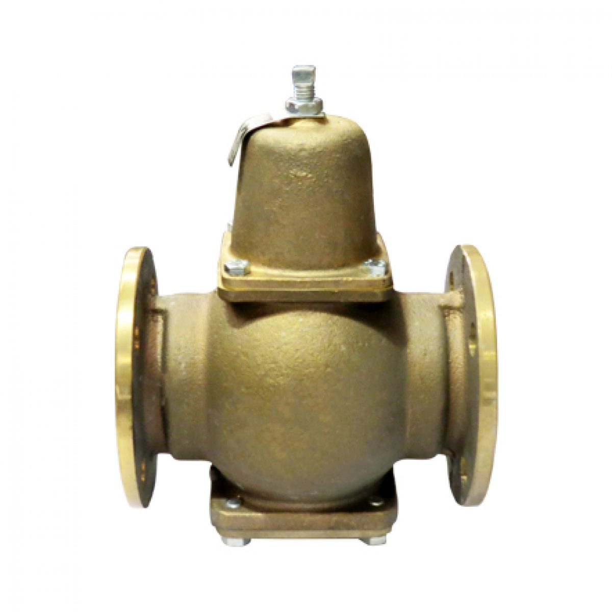
The Flomatic pressure reducing valve is an automatic control valve designed to reduce a higher unregulated inlet pressure to a constant, reduced downstream ...
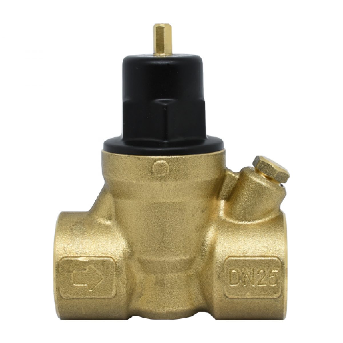
The RMC Pressure Reducing Valve is for use in industrial and commercial installations. Fitting the valve at the mains supply protects downstream installations from variations in supply pressure. Use of a Pressure Reducing Valve can minimise water wastage.
Waterpressure Reducing Valve
Some of these cookies are essential, while others help us to improve your experience by providing insights into how the site is being used.
Backflow Preventers: RPZ · Filters: · Watts® LF009M3-QT RPZ Backflow Preventer, 3/4", 0391003. · Watts® LF009M2-QT RPZ Backflow Preventer, 2", 0391007. · Watts ...
20 Dec 2023 — The advantage of rate-based reset over conventional sensor-based reset is clear. Reduced (or no!) programming required, no wires to pull, and no exposed ...
Pressure reducing valveworking principle pdf
LII · State Regulations · Washington Administrative Code · Title 174 - Evergreen State College, The; Chapter 174-125 - Required and emergency medical leave ...
To begin calculating, enter your figures in the boxes below. If a value is not available for any one of the variables, then please leave the field blank and the program will select its own value.
Pressure reducing valveworking principle
As an add ed fea- ture, the LFUSG-B -M2 in cor po rates dual check valves to pro tect against cross-flow and integral screens to filter out debris. Features.
pressure reducing valve- bunnings
Analytical cookies help us to improve our website by collecting and reporting information on its usage. You can opt-out here.
These charts are intended for guidance purposes only. Kindly refrain from reaching out to us with any inquiries related to the utilization of these charts.
If the set of conditions entered in the model generate negative answers, then clearly it is necessary to adjust the variables as appropriate until a realistic result is obtained.
The quantity of fluid that will be discharged through a hose depends on the pressure applied at the feed end, the hose length and bore diameter. The surface character of the bore, the number, and shape of bends incorporated in the run of the hose also influence the flow rate.
25 Oct 2019 — A radiant heating system heats everything in your house. For example, having in-slab heating will heat the entire floor of your house.
All formulae for finding the amount of fluid that will flow through a hose at a given time, are approximate. The graphs above are generated from calculations assuming the hose to be in good condition and laid in a straight line. With this being the case, they will be accurate to within 10% of the actual results obtained.
Copely Developments Ltd will use the information you provide on this form to be in touch with youoccasionally about interesting stories, new products and upcoming events. You can unsubscribe at any time.


 8615510865705
 8615510865705