
Pwm Vacuum Switching Valve - vacuum switching valve
To determine the required expansion tank size, you need to calculate the total volume of the system, including the volume of water in the pipes, radiators, and other components. You should also consider the maximum expected temperature change in the system, as well as the pressure rating of the equipment and piping components. Using formulas such as the one provided in the ASHRAE Handbook or other industry resources, you can calculate the required tank size based on these factors. It’s essential to consult with a qualified engineer or technician to ensure accurate calculations and proper tank sizing.
Expansion tank sizingrule of thumb
Regular inspection and maintenance of the expansion tank are crucial to ensure optimal system performance and prevent potential issues. It’s recommended to inspect the tank at least annually, checking for signs of corrosion, damage, or leakage. Additionally, the tank should be drained and cleaned periodically to remove sediment and debris that can affect its performance. The frequency of maintenance may vary depending on the system design, operating conditions, and local regulations. Consult with a qualified technician or the tank manufacturer’s guidelines for specific maintenance recommendations.
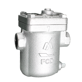
This type of steam trap utilizes the difference in density between steam and condensate, and uses the buoyancy of an open float that takes the form of a bucket to open and close a valve. Miyawaki inverted steam traps include the low-discharge ES Series and the high-discharge ER Series. Both the series use Miyawaki’s SCCV System* for the valve, which offers superb durability and valve closing performance. In addition, ER Series products use a differential pressure double valve system to achieve high discharge, which allows them to discharge the same volume while being much smaller in comparison to other companies’ inverted bucket traps.
Hydronic expansion tank sizingpdf
This type of steam trap utilizes the expansion and contraction of wax caused by the temperature difference between steam and condensate to open and close a valve. Uses These steam traps are suitable low pressure, small scale systems such as heating radiators.
For higher desired precharge pressures, either a special order can be made from the factory or the contractor must increase the pressure with compressed air or a hand pump. But it is not uncommon for this to be overlooked. This oversight can be compensated for by sizing the tank using Equation below (assuming atmospheric pressure at sea level):
Expansion tank sizingcalculator
A steam trap is an automatic valve that removes condensate and air from a steam system. Miyawaki steam traps swiftly remove condensate from pipes and devices or equipment that use steam, and ensure that facilities run stably and that steam can be used effectively.
This type of steam trap utilizes the difference in temperature between steam and condensate, and uses the expansion and contraction capacity of a thermosensitive body to open and close a valve. Temperature control steam traps are thermostatic traps that enable the temperature at which they operate to be freely set in advance, and which Miyawaki led the world in the development of as an energy saving trap for steam tracing use. With a high reliability backed up by a proven track record, these steam traps have been adopted by a wide variety of industries around the world. They are comprised of sturdy internal components that can withstand pressure and shocks, and can also handle the demands placed on steam traps for main steam pipes that contain high-pressure areas and superheated steam. Uses Temperature control traps are used to maintain the temperature in steam trace lines and process condensate in main steam pipes. Miyawaki offers a variety of temperature control traps to deal with different pressure areas, ranging from low pressure to extra-high pressure areas.
This equation includes the credit for the expansion of the piping system. This term is also relatively small and the expansion coefficients are hard to determine given the various materials in the system, but it is included in Equation above since it is included in the ASHRAE Handbook sizing equations. This term is also included in some, but not most, expansion tank manufacturers’ selection software. Most manufacturers conservatively ignore this term since it is small and no larger than the terms already ignored in the above Equation. Ignoring this term results in Equation below:
Hydronic expansion tank sizingcalculator
This was the first design of a compression tank that included an air/water barrier (a flexible membrane, to eliminate air migration) and that was designed to be precharged (to reduce tank size). The flexible diaphragm typically is attached to the side of the tank near the middle and is not field replaceable; if the diaphragm ruptures, the tank must be replaced.
ASME Boiler and Pressure Vessel Code-2015, Section VI, includes sizing equations (as do the UMC and IMC, which extract the equations verbatim), as shown in Equation below, with variables revised to match those used in this article:
Note that this equation only applies when the tank is precharged to the required Pi . Tanks are factory charged to a standard precharge of 12 psig (83 kPag).
This type of steam trap utilizes the hydrodynamic properties that occur due to differences in the flow velocity between steam and condensate and thermodynamic properties to open and close a valve. Disk traps have no limitations in terms of installation orientation, making them very easy to use. The SV1 has a built-in bypass valve which means no bypass pipe is required, thus enabling savings in terms of piping materials and a large reduction in the time required for installation work.
Bladder tanks use a balloon-like bladder to accept the expanded water. Bladders are often sized for the entire tank volume, called a “full acceptance” bladder, to avoid damage to the bladder in case they become waterlogged. Bladders are gener ally field replaceable. This is now the most common type of large commercial expansion tank.
Hydronic expansion tank sizingformula
Expansion tanks are a necessary part of all closed hydronic systems to control both minimum and maximum pressure throughout the system. Expansion tanks are provided in closed hydronic systems to (1) accept changes in system water volume as water density changes with temperature to keep system pressures below equipment and piping system component pressure rating limits. Also, (2) maintain a positive gauge pressure in all parts of the system to prevent air from leaking into the system. (3) Maintain sufficient pressures in all parts of the system to prevent boiling, including cavitation at control valves and similar constrictions. (4) Maintain net positive suction head required (NPSHR) at the suction of pumps.
Unless precharged to the minimum operating pressure prior to connection to the system, this style of tank also must be larger than precharged tanks. Accordingly, this design is also almost never used anymore.
The numerator is the volume of the expanded water, Ve , as it warms from minimum to maximum temperatures, so the equation can be written:
While standard formulas can provide a good starting point for calculating expansion tank size, there are other factors to consider, such as system complexity, piping layout, and equipment specifications. For example, systems with multiple loops or zones may require larger tanks to accommodate the additional volume changes. Additionally, the type of fluid used in the system, such as water or glycol, can affect the tank sizing calculation. It’s essential to consider these factors and consult with industry resources or a qualified engineer to ensure accurate tank sizing.
Chilled waterexpansion tank sizing
The general formula for tank sizing, Equation 1 (with variable names adjusted to match those used in this article), from basic principles assuming perfect gas laws:
For any tank that is precharged to the required initial pressure, including properly charged diaphragm and bladder tanks, but also including closed plain steel tanks if precharged, Ps is equal to Pi so the sizing equation reduces to:
Temperature difference between steam and condensate Diaphragm steam traps are based on a thermoelement (diathermo) that changes shape in response to temperature. Miyawaki’s D Series diaphragm traps include many stainless steel products with superb anti-corrosion properties, and they have been kept as small as possible to enable them to be installed in tight spaces. The DV1 also has a built-in bypass valve which renders a separate bypass pipe unnecessary, enabling a large reduction in product and pipe installation costs. There are two types; one with a thermoelement operating temperature 5℃ lower than the saturation temperature, and one with a thermoelement operating temperature 15℃ lower than the saturation temperature.
The last term (0.02 Vs ) accounts for additional air from desorption from dissolved air in the water. This equation can be simplified to Equation below by ignoring small terms and assuming tank temperature stays close to the initial fill temperature (typically a good assumption, assuming no insulation on the tank or piping to it, which is a common, and recommended, practice):
This is the same tank style as the vented tank, but with the vent capped. This allows the tank to be located anywhere in the system and work with higher temperatures. But they still have the air/water contact that allows for corrosion, and sometimes a gradual loss of air from the tank as it is absorbed into the water.
Comparing the denominator of this Equation to Equation for Closed Tank (no precharge), this formula is clearly for sizing a nonprecharged tank; it will overestimate the size of a precharged tank. The numerator is a curve fit of Ve ; it assumes a minimum temperature of 65°F (18°C) and is only accurate in the range of about 170°F to 230°F (77°C to 110°C) average operating temperature. Therefore, this equation cannot be used for very high temperature hot water (e.g. 350°F [177°C]), closed-circuit condenser water, or chilled water systems.
Hydronic expansion tank sizingaustralia
Undersizing an expansion tank can lead to several consequences, including increased system pressure, reduced system efficiency, and potential equipment damage. Insufficient tank capacity can cause the system to exceed the pressure rating of equipment and piping components, leading to premature failure or even catastrophic failure. Additionally, undersizing can result in inadequate pressure maintenance, allowing air to enter the system and causing corrosion, erosion, and other issues.
Since they are vented, open tanks must be located at the highest point of the system. Water temperature cannot be above 212°F (100°C), and the open air/water contact results in a constant migration of air into the system, causing corrosion. Accordingly, this design is almost never used anymore.
For unvented plain steel tanks, the starting pressure is typically atmospheric pressure with the tank empty (no precharge). The tank is then connected to the makeup water, which pressurizes the tank to the fill pressure by displacing air in the system, essentially wasting part of the tank volume. So the sizing equation is:
Hydronic expansion tank sizingchart
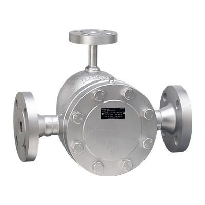
This type of steam trap utilizes the difference in density between steam and condensate, and uses the buoyancy of an airtight ball-shaped float to open and close a valve. Steam traps that use floats include those with a mechanism in which the force from the buoyancy of the float is transferred to the valve via a lever (lever-float steam traps) and those in which the float itself simultaneously works as a valve without a lever mechanism (lever-free steam traps). Some lever float steam traps use a double ported balance valve system* that enables a high discharge to be achieved by a small unit.
For vented tanks, the pressures are all the same and the dominator limits to 1, so the tank size is simply the volume of expanded water:
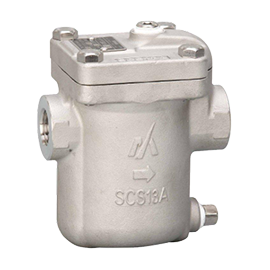
All models are made of stainless steel body and stainless steel internals. They can be installed either horizontally or vertically. Two-bolt connection for simplified replacement of the steam trap.
Open expansion tanks are vented to the atmosphere and are typically used in open systems where the tank is not pressurized. Closed expansion tanks, on the other hand, are pressurized and used in closed systems where the tank is subjected to system pressure. Closed tanks are more common in modern hydronic systems due to their ability to maintain a positive pressure and prevent air from entering the system. Open tanks are often used in older systems or in applications where the system pressure is relatively low. The choice between open and closed tanks depends on the specific system requirements and design.
The latter two points generally apply only to high temperature (greater than approximately 210°F [99°C]) hot water systems. For most HVAC applications, only the first two points need to be considered.


 8615510865705
 8615510865705